Miata Variable-Speed Intermittent Wiper Control
Ever since I got my Miata, I was dismayed at the lack of a variable-speed intermittent
wiper setting. Such variable-speed intermittent wipers have been standard on most cars
since the early 90ies. It is strange that Mazda, even in the latest Miatas still does
not provide this feature.
There have been some discussions on Miata.net (here and here) but the workarounds discussed there weren't enticing to me.
So I finally set out to find the "ultimate solution" (ultimate for me, anyway.)
This page describes how to add variable speed to the intermittent wiper control of a 1999 Mazda Miata.
This modification was tested on a 1999 US model Miata ONLY! It may or may not work on Miatas from other years or on Miatas sold outside the US.
Figure 1 shows the solder side of the wiper control circuit in the '99 Miata. Figure 2 shows the component side.
The Workshop Manual provides a basic wiring diagram of the wiper and washer, but leaves out all the electronics.
After several false starts, I found out that the circuit board actually is already prepared for a variable-speed intermittent control, but for whatever reason, Mazda did not add the 2 resistors needed for it...
Figure 3 shows where the 2 resistors are added: a 10 kOhm resistor (I used an SMD resistor, but a normal resistor works just as well,) at the red circle, and a a 100 kOhm potentiometer or wires leading to an external pot at the green circle.
Since these resistors are connected in parallel with the existing 36 kOhm resistor, the resulting resistance is less than 36 kOhm. To keep the maximum delay in the previous range, I also replaced the existing 36 kOhm resistor (circled in blue) with a 47 kOhm one. That's of course strictly optional.
Update: after feedback from people on the miata.net forum and some experimentation I put a 100 kOhm resistor in there. I found I like the extended range better ;-)
There have been some discussions on Miata.net (here and here) but the workarounds discussed there weren't enticing to me.
So I finally set out to find the "ultimate solution" (ultimate for me, anyway.)
This page describes how to add variable speed to the intermittent wiper control of a 1999 Mazda Miata.
This modification was tested on a 1999 US model Miata ONLY! It may or may not work on Miatas from other years or on Miatas sold outside the US.
I do NOT take any responsibility for
any harm this description may cause.
USE AT YOUR OWN RISK!
USE AT YOUR OWN RISK!
The combination switch
A check of the 1999 Miata Workshop Manual showed that the windshield wiper control circuit is part of the light/signal/wiper combination switch. The instructions to remove the combination switch call for removal of the steering wheel, which I wanted to avoid since I have a lot of respect for the air bag module and I didn't want to touch that... I also didn't want to experiment and potentially destroy the wiper control circuit in my car, so I bought a used combination switch from one of the companies that sell car parts from accident cars.The wiper control circuit
A circuit for a variable-speed intermittent wiper is in principle quite simple: A capacitor is charged through a resistor. Once the capacitor is charged, it opens a transistor which switches a relay. Varying the resistor value changes the time it takes to charge the capacitor. Switching between multiple resistors of different values or using a potentiometer makes the time variable.Figure 1 shows the solder side of the wiper control circuit in the '99 Miata. Figure 2 shows the component side.
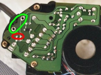
Figure 1
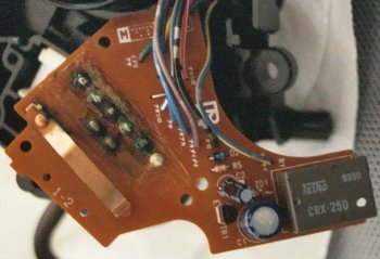
Figure 2
The Workshop Manual provides a basic wiring diagram of the wiper and washer, but leaves out all the electronics.
After several false starts, I found out that the circuit board actually is already prepared for a variable-speed intermittent control, but for whatever reason, Mazda did not add the 2 resistors needed for it...
Figure 3 shows where the 2 resistors are added: a 10 kOhm resistor (I used an SMD resistor, but a normal resistor works just as well,) at the red circle, and a a 100 kOhm potentiometer or wires leading to an external pot at the green circle.
Since these resistors are connected in parallel with the existing 36 kOhm resistor, the resulting resistance is less than 36 kOhm. To keep the maximum delay in the previous range, I also replaced the existing 36 kOhm resistor (circled in blue) with a 47 kOhm one. That's of course strictly optional.
Update: after feedback from people on the miata.net forum and some experimentation I put a 100 kOhm resistor in there. I found I like the extended range better ;-)
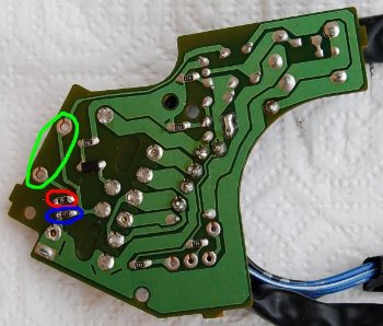
Figure 3
Installation in the car
With the circuit demystified, the actual installation in the car was the only thing left. As I mentioned above, I didn't want to remove the steering wheel. It is possible, but not easy, to get to the wiper circuit without steering wheel removal.- Disconnect the negative battery terminal.
- Remove the cover around the steering column (figure 4.)
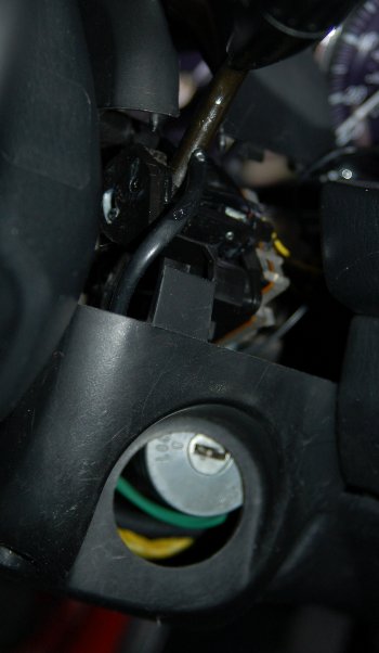
Figure 4 - Remove the instrument hood and instrument panel.
- Use a stubby Phillips screwdriver (there is no space for a normal
screwdriver) to remove the two screws that hold the plastic cover and the wiper
control circuit (you can't see the screws, so you pretty much have to feel them, or use
a small pocket mirror or cosmetic mirror.)
See the red circles in figure 5 for the location of the screws.
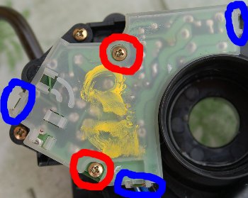
Figure 5 - Remove the plastic cover (it is clipped at 3 positions (blue circles
in figure 5), and carefully lift the wiper circuit board from its clip (red circle
in figure 6.)
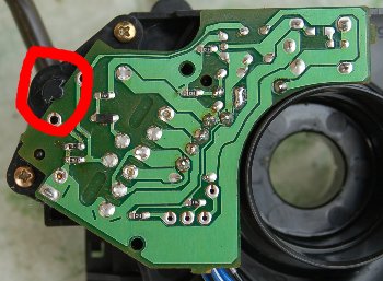
Figure 6 - Twist the wiper circuit board so that you get access to the solder
side. Watch out to not shift the white plastic piece with the contacts that is operated
by the wiper stalk (figure 7). It hooks into the stalk (figure 8), and if it shifts or
falls out, put it back in with the hook facing upward, and make sure that it wraps
around the stalk and moves with it, and wasn't inserted below or above the stalk.
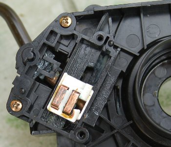
Figure 7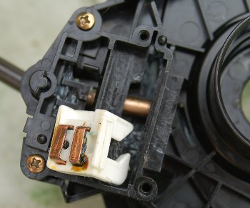
Figure 8 - Solder the 10 kOhm resistor and wires for the 100 kOhm potentiometer onto the circuit.
- Put the circuit board back into place, and screw it in, making sure the sliding contacts are correctly in place.
- Find a convenient position to place the potentiometer. I used a
thumbwheel resistor and put it at the right side of the instrument panel hood.
I used a glue gun to fix the potentiometer in the position.
Other possible positions: right next to the wiper stalk, or next to the panel light thumbwheel. - Attach the 100 kOhm potentiometer to the wires sticking out from the wiper control. One wire is soldered to the middle terminal of the potentiometer. The second wire needs to be soldered to one of the terminals on either side, depending on how the potientiometer is mounted. If the delay setting works backwards, move the second wire to the terminal on the other side of the potentiometer.
- Put the instrument panel, panel hood, and steering column cover
back into place. Figure 9 shows the final look.
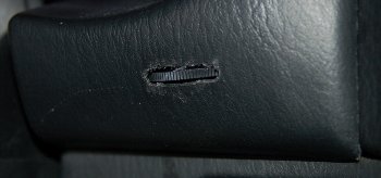
Figure 9
Parts needed
- 10 kOhm resistor.
- 100 kOhm potentiometer, linear taper, e.g., a thumbwheel pot (Mouser Electronics, type 311-1700-100K with switch, type 311-1600-100K or 311-1206F-100K without switch) or a normal single-turn pot.
- Knob for the potentiometer (for a thumbwheel pot, e.g., the one that comes with the 311-1206F-100K pot from Mouser.)
- Optionally, 47 kOhm resistor to replace the 36 kOhm SMD resistor.